 |
| August 14, 2012 | Volume 08 Issue 30 |
Designfax weekly eMagazine

Archives
Partners
Manufacturing Center
Product Spotlight
Modern Applications News
Metalworking Ideas For
Today's Job Shops
Tooling and Production
Strategies for large
metalworking plants
Wheels:
Modeling optimizes a piezoelectric energy harvester used in car tires
Siemens is using fluid-structure interaction simulation to ensure the cost-effective optimization of a cantilever in a MEMS generator designed to power a tire pressure monitoring system.
By Jennifer Hand
CO-AUTHORED BY DR. INGO KUEHNE AND DR. ALEXANDER FREY, SIEMENS AG
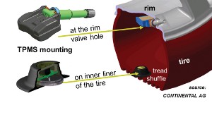
Figure 1. TPMS mounting options - on the rim or on the inner lining of the tire.
The desire to get rid of batteries and power lines motivates a wide range of research. In the quest for systems that are energy autonomous, the concept of energy harvesting attracts a lot of attention. Combine this idea with operation at the micro level, and the "what if" scenarios become even more enticing.
For researchers at Siemens Corporate Technology in Munich, there was a strong attraction for exploring the potential of an energy harvesting MEMS (micro electro-mechanical system) generator. Dr. Ingo Kuehne explains, "Our remit is broad. We are looking to develop platform technologies for tomorrow rather than specific products; however, it makes sense to demonstrate the value of our research. Together with our partner Continental AG, we decided to focus on an application with clear commercial potential. Our ultimate goal is to design the MEMS generator to be as small, light, and strong as possible with enough energy to power a system under a range of conditions."
They chose to design a microgenerator for an innovative tire pressure monitoring system (TPMS) driven by motion. Because TPMS units are traditionally powered by batteries, they tend to be mounted on the wheel rim. With no reliance on a battery, such a system could be placed inside the tire and would be in a position to measure much more than pressure (Figure 1). It could monitor temperature, friction, wear, and torque; assist with optimal tracking and engine control; and convey all this critical information wirelessly. It would also be maintenance free, low cost, and environmentally friendly. Yet, locating the device within the tire requires that the assembly be extremely robust and able to withstand gravitational acceleration up to 2,500 g. Moreover, in order to avoid tire imbalance it would have to be very light, and in terms of operational life it would need to match that of a tire, a minimum of 8 years.
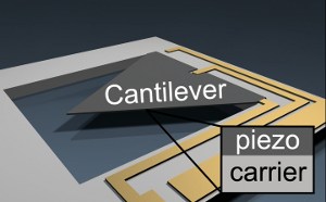
Figure 2. Schematic of the piezoelectric MEMS generator energy harvester. The cantilever is made of two materials and electrical energy is transferred through the circuit from the cantilever.
From mechanical stress into electrical energy
Mounted to one spot on the inside of a tire, a piezoelectric microgenerator would be able to harvest energy from the compression created each time that particular area of the tire touched the ground. The cantilever was designed to incorporate a thin film of self-polarized piezoelectric ceramic material with a silicon carrier layer, which provides mechanical stability and stores harvested mechanical energy (Figure 2).
The team had settled on a triangular design for the spring-loaded piezoelectric cantilever, as such a shape enables a uniform stress distribution in the surface direction. "Typical cantilever designs have substantial mass and are heavy with a concentrated weight at the tip. This is fine for the conventional method of continuously exciting a cantilever at its natural frequency. However, the high dynamic forces we are dealing with prevent us from using this method of excitation," says Dr. Alexander Frey. "We had to adopt an unconventional approach and avoid mass and its concentration. This, in turn, gave us a more serious problem because damping becomes much more critical."
The big question for the Siemens team was how to optimize the design of the cantilever in order to minimize damping. It appeared that air damping was the dominant effect, and the aerodynamic profile was a critical parameter. While the cantilever area was limited to 100 mm2, the layer thicknesses were design parameters that could be freely changed. "We needed to find suitable values for these parameters so that we could ensure that the mechanical oscillation would continue for as long as possible, and transfer as much of the mechanical energy as possible to the electrical domain," says Dr. Frey. "We really needed a numerical tool to determine the optimal structure and ensure that enough energy was being produced."
Fluid and structure: An open relationship
Identifying the transfer of mechanical energy to the surrounding air as being critical, the team first conducted a fluid-structure interaction (FSI) analysis of the cantilever. Dr. Kuehne explains, "We started with static simulations and these gave us some initial values. Then, a time-dependent analysis allowed us to see a range of physical effects and understand the impact of the surrounding air on the damping of the cantilever." (Figures 3 and 4)
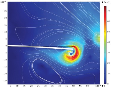
Figure 3. 2D fluid-structure interaction simulation showing the resulting velocity field caused by feeding mechanical cantilever energy into the disordered kinetic energy of the surrounding gas.
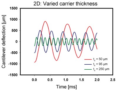
Figure 4. 2D simulations of fluid-structure interaction on a cantilever's deflection at a gas pressure of 1 bar for varied carrier thickness.
Members of the team went on to conduct a 3D FSI simulation and to consider the cantilever deflection as a function of external pressure and carrier thickness (Figures 5 and 6). They examined the maximum stress required for initial deflection at each thickness where, as Dr. Frey reports, "We confirmed quantitatively that increasing the thickness of the cantilever led to an improvement in the damping behavior of the MEMS harvester."
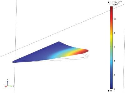
Figure 5. 3D fluid-structure interaction simulation showing the deflection of the triangular cantilever.
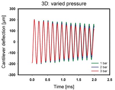
Figure 6. 3D simulations of fluid-structure interaction on a cantilever's deflection as a function of gas pressure with a carrier thickness of 250 μm.
Optimizing cantilever size and shape
"With COMSOL Multiphysics simulation software, we learned how to numerically describe the behavior of our structure to then allow us to conduct research in the laboratory," says Dr. Kuehne. In order to compare the simulated behavior with experiments, the cantilever was periodically excited and the generated piezoelectric voltage was recorded. "Comparison of the simulation with physical testing revealed that the overall damping behavior was actually higher. The obvious explanation was that we were losing energy because of intrinsic losses in the material. We assumed an accepted value for this internal damping, and after taking these correction factors into account, we arrived at the same results. This reassured us that our simulation process with COMSOL was reliable and that we could continue to investigate the performance of the cantilever using different parameter values." The team was then able to move on to optimizing system components and system integration (Figure 7).
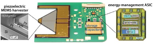
Figure 7. Prototype of a piezoelectric MEMS energy harvesting module and surrounding system.
The use of COMSOL was critical to the development of the physical prototypes. According to Dr. Kuehne, it takes three people four months to do one technological run, which typically consists of one batch of up to 25 wafers.
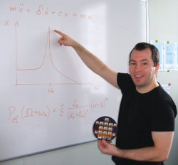
Dr. Ingo Kuehne holding one of the wafers used in the production of the MEMS energy harvester prototypes.
"One run usually results in a couple of complete prototypes, depending on layout," says Dr. Frey. "Testing takes a further two months. In particular, the extra expense of a clean room infrastructure results in development costs of more than 100,000 Euros for a single prototype run over six months. In contrast, you can measure a 2D simulation in hours and a 3D simulation in days. In that sort of time it is easy to simulate the performance of up to 2,000 different prototypes within COMSOL Multiphysics.
"Without COMSOL and the option of numerical modeling we would have to make numerous physical structures that would have been time-consuming and expensive. Instead, we were able to get on with the process of optimizing the MEMS design."
Learn more about this research by clicking here.
Source: COMSOL News 2012, reposted with permission from COMSOL.
Rate this article
View our terms of use and privacy policy